Thursday, September 24, 2026

Computer UPS & Low Capacity Home Inverter Technology

Introduction

RB World Micro introduces an advanced Computer UPS and Home Inverter Technology specially developed for UPS technicians, electronics technicians, service engineers, and small-scale UPS manufacturers.

This technology provides a practical platform for developing reliable Computer UPS as well as Home Inverter systems, without requiring technicians to design every major section of the system completely from the beginning.

The technology includes a specially designed UPS PCB, transformer design and specifications, battery compatibility, technical information, and complete technical support required for system development and servicing.


Specially Designed for LiFePO₄ Battery Applications

One of the key features of this UPS technology is its special design for LiFePO₄ (Lithium Iron Phosphate / LFP) battery applications.

The system can be configured with a 15Ah LiFePO₄ battery, making it suitable for compact and efficient UPS applications.

At the same time, the technology also supports 15Ah Lead-Acid batteries.

Therefore, technicians can use the technology with either:

  • 15Ah LiFePO₄ (LFP) Battery
  • 15Ah Lead-Acid Battery

The appropriate charging parameters, protection system, and battery configuration must be selected according to the battery chemistry being used.

This dual-battery support gives technicians greater flexibility when developing different UPS and inverter configurations.


Advanced UPS PCB Technology

The heart of the system is its specially designed UPS PCB.

The PCB is controlled by a Microchip PIC16F72 microcontroller, which provides the required control functions for the UPS system.

The PCB is designed to be supplied to technicians so that they can build and develop their own Computer UPS or Home Inverter systems using the provided technology.

Key PCB Features

  • Microchip PIC16F72 microcontroller
  • Specially designed UPS control system
  • Suitable for Computer UPS applications
  • Suitable for Home Inverter applications
  • Designed to support LiFePO₄ and Lead-Acid battery configurations
  • Suitable for different system configurations depending on the required output
  • Technical information and support provided to technicians

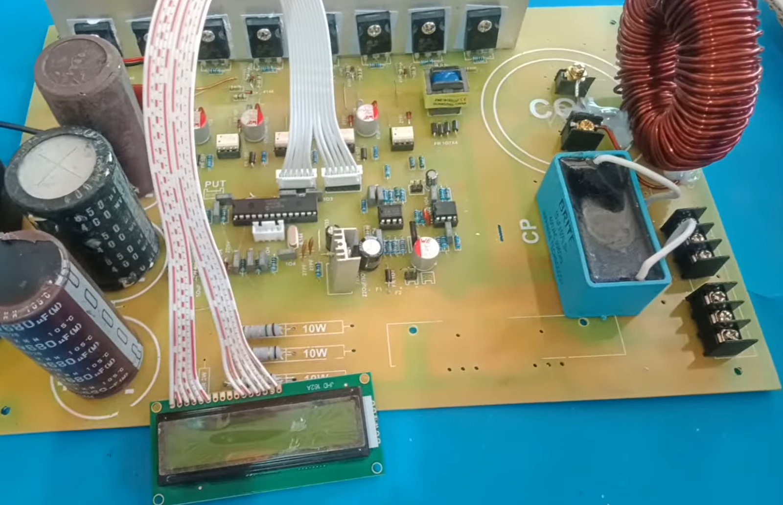
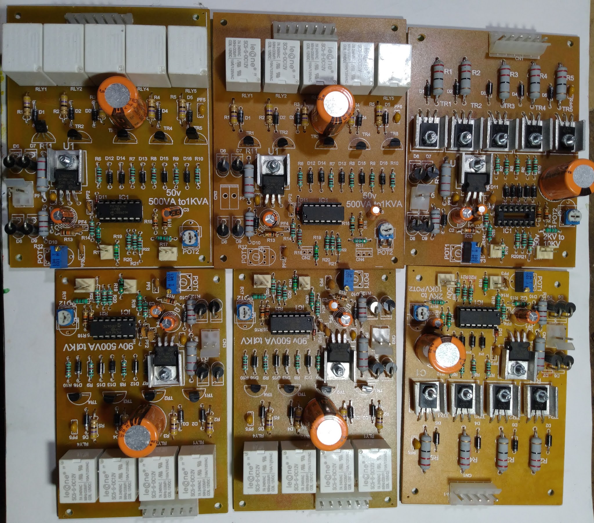
PCB Picture :-


These PCB images can be placed here to show the actual PCB design, component layout, and overall construction of the UPS control board.


Transformer Design & Technology

The transformer is another important part of the complete UPS system.

RB World Micro provides the required transformer design and specifications along with the UPS technology. This helps technicians understand the transformer requirements for building the appropriate UPS or inverter configuration.

The transformer specification can be selected according to the required system power, output configuration, battery voltage, and application.

This makes it easier for technicians to build the complete system using the supplied PCB and transformer design information.

Transformer Picture :- 


These pictures can be used to show the actual transformer construction and design used with the UPS technology.


Computer UPS & Home Inverter Applications

The same core technology can be used for both Computer UPS and Home Inverter applications.

Depending on the required configuration, technicians can use the technology to develop systems for:

  • Computer UPS
  • Desktop computer backup systems
  • Small office UPS applications
  • Home backup systems
  • Home Inverter applications
  • Small electronic equipment backup
  • Other suitable low-power backup applications

The flexibility of the PCB, transformer design, and battery configuration allows technicians to develop different system versions according to their requirements.


300VA / 400VA Power Applications

The UPS technology can be used for applications up to 300W and up to 400W, depending on the selected configuration.

The actual usable output power depends on several technical factors, including:

  • Transformer rating
  • PCB configuration
  • Battery discharge capability
  • Battery/BMS specifications
  • System efficiency
  • Output stage configuration
  • Connected load

Therefore, the appropriate PCB, transformer, battery, and other components should be selected according to the required power level.


15Ah Battery Configuration

The technology supports 15Ah battery applications.

For LiFePO₄ applications, a 15Ah LiFePO₄ battery can be used with the appropriate BMS and charging configuration.

The technology also supports a 15Ah Lead-Acid battery, provided that the charging and protection parameters are correctly configured for Lead-Acid chemistry.

Supported Battery Types

15Ah LiFePO₄ Battery
Lithium Iron Phosphate battery technology for suitable UPS and inverter applications.

15Ah Lead-Acid Battery
Lead-Acid battery option for applications where this battery chemistry is preferred.

The selected battery type should always be matched with the correct charging, protection, and system configuration.


Complete UPS / Inverter Cabinet

The complete technology can be assembled into a compact UPS or inverter cabinet.

The cabinet can accommodate the required PCB, transformer, battery connections, wiring, protection components, and other necessary parts according to the selected configuration.

The open-cabinet design also allows technicians to understand the internal arrangement of the system and makes servicing and maintenance easier.

UPS Cabinet Picture :- 


These cabinet images can be used to show the internal arrangement and overall construction of the complete UPS/Inverter system.


Complete Technical Support for Technicians

RB World Micro provides not only the PCB but also the necessary technical information required to work with the technology.

The support includes:

  • UPS PCB
  • PIC16F72-based control technology
  • Transformer design
  • Transformer specifications
  • Battery configuration information
  • LiFePO₄ battery application information
  • Lead-Acid battery application information
  • System configuration guidance
  • Technical information
  • Required development support

This allows technicians to focus on system assembly, testing, servicing, and production instead of developing every individual section from scratch.


What We Provide

With this technology, technicians can receive the major technical building blocks required to develop their own Computer UPS or Home Inverter system.

Technology Support Includes:-

1. UPS PCB
A specially designed UPS control PCB operated by the Microchip PIC16F72 microcontroller.

2. Transformer Design
Required transformer design and specifications for the appropriate UPS/Inverter configuration.

3. Battery Compatibility
Support for both 15Ah LiFePO₄ and 15Ah Lead-Acid battery configurations, with the appropriate charging and protection requirements.

4. Technical Information
Necessary technical information for system development, assembly, testing, and servicing.

5. Technical Support
Support for technicians working with the technology and developing their own UPS/Inverter systems.


A Practical Technology Platform for UPS Technicians

For technicians who want to develop Computer UPS and Home Inverter systems, this technology provides a practical starting point with the major technical sections already designed.

Instead of developing the complete control system, transformer specifications, and battery-related configuration completely from the beginning, technicians can work with the provided technology and technical information.

The PIC16F72-based UPS PCB, transformer design, 15Ah battery support, and technical assistance together provide a complete technology platform for suitable UPS and inverter applications.


Important Technical Note

The performance of the final UPS or inverter depends on the complete system configuration.

Output power, backup time, charging performance, battery life, and overall efficiency may vary depending on the transformer, PCB configuration, battery type, BMS, battery discharge capability, connected load, wiring, and other system components.

For LiFePO₄ and Lead-Acid batteries, the charging and protection parameters must be correctly matched to the selected battery chemistry.

The 15Ah LiFePO₄ and 15Ah Lead-Acid batteries are alternative supported battery configurations and should not be connected together as different battery chemistries in the same system unless a specifically designed system permits it.


Get the Technology from RB World Micro

If you are a UPS technician, electronics technician, service engineer, or small-scale UPS manufacturer looking for a practical technology platform for developing Computer UPS or Home Inverter systems, RB World Micro provides the required PCB, transformer design, technical information, and support.

With PIC16F72-based control technology, 15Ah LiFePO₄ and Lead-Acid battery support, transformer design, and complete technical guidance, you can develop suitable UPS and inverter systems according to your required configuration.

RB World Micro

Computer UPS & Home Inverter Technology
PCB + Transformer Design + Battery Support + Technical Support

For technical details, product information, and further assistance, contact RB World Micro. 

Saturday, July 25, 2026

Solar Inverter Off Grid Without Battery

 Now We Are Ready to go with this Product.

For Any query, Firstly must contact on WhatsApp Before Make Any Call.


For Any Enquiry, First contact on WhatsApp. 


Sunday, December 8, 2024

Off Grid Solar Inverter Without Battery

 Very soon We Launch Solar Inverter without battery which is totally different from on-grid & off-grid inverter.


Friday, August 5, 2022

HOME REGULATOR (SMPS BASED) FOR AC MAINS FLACTUATION & LOW HI VOLTAGE PROBLEM

Why use this?

 We all face a common problem in our home that our mains line voltage change several time within a day. It's mainly varies in summer & winter season. Another big problem is after cutoff the line voltage when it's comeback, the line voltage apply suddenly surge voltage to our home appliances & due to this, many time our costly home appliances damage permanently.
 
 Many of the people try to overcome this problem by using voltage stabilizer. This is a good idea. But when a whole house connected from a Transformer based Relay operated voltage stabilizer, during the voltage fluctuation period all lighting system & all fan are facing more or less up to 40-50v fluctuation & so, those are continuously facing the high-low voltage problem. 


   Contact :- +91-9339470435, +91-9831509479
                                                    (Any Day 4 pm to 9 pm)

 The smps based voltage regulator not operate by iron core transformer, nor using tap combined relay. It's run just by PWM technology. So it's run smoothly & main the output voltage by 1-2% maximum tolerance. No load consumption of this device is just only 1-2Watt. So as an voltage stabilizer character, it's also a energy saver device.

Feature of this Product:-

1. Wide Input voltage range like 150-300v ac.

2. Fixed output voltage 225v (1-2% tolerance)

3. Soft start facility. At the starting time the out voltage increasing smoothly from 0.

4. Overload Protection. 

5. Short circuit protection.

6. Mains input voltage Hi-Low Protection.


 Product going ready for sale very soon...….


Tuesday, March 1, 2022

CONSTANT CURRENT CHARGER 3V TO 65V 10AMP

   It's a great product for Battery industry for maintain a battery life when maintain the charging process by this charger with battery. Also it's another better use is for service the battery & when making the battery plate's. This charger maintain the constant charging current where it's current is adjust, because it's very user-friendly charger for adjust the current. We manufacture the various charging current range of charger according to requirement. 


  Operation :- The adjustable charging current range is 0.25 amp to 10amp. it's doesn't matter that the battery is 1 or 4. The maximum range of battery charging of this charger is presently 4 battery(48v battery). The maximum range of charging current is up to 50amp for customize product. The charging current tolerance after adjustment is only 0.5%-1 % of the charging current. So, never ever see the voltage label when the charger is in manual mood, because the charger have 2 mood, auto and manual. In auto mood, the charger have 1battery, 2 battery & 4 battery auto charge complete function, whereas in manual mood it's not have this. So, in manual mood the charger continuously charge the battery at fixed current where the current is last adjusted.  


More details coming Soon..........


        Contact :- +91-9339470435, +91-9831509479
                                                    (Any Day 4 pm to 9 pm)

Sunday, July 19, 2020

Best Quality Automatic Stabilizer Transformer Winding wire gauge selection Calculation Process


Contact :- +91-9339470435, +91-9831509479
                                                         (Any Day 4 pm to 9 pm)


Today we discuss only about wire gauge selection, not about total transformer winding process.

  When you construct an Automatic Stabilizer Transformer, the most vital thing is to calculate the wire gauge of the winding. If the wire gauge is not equal with the minimum required rated current according to the output load, you got so far voltage drop to the output within no-load & on-load condition.

   This is normal fact in every coil related product that when a load is connect on the coil, some voltage drop must be happen due to coil resistance, this is normal case. That's why when you select the wire gauge for winding a coil, you must maintain the minimum wire gauge according to the rated current with respect of required output load.

  If the wire gauge is so lower than required, you found more & more voltage drop within no-load & on-load condition.

  Also if the wire gauge is so lower than required, you found more & more temperature difference within no-load & on-load condition.  You got maximum temperature from transformer when it's maintain 50%-60% load on output & if the transformer running  long time on this situation, you found it's coil can burn out at certain stage.

  So, wire gauge selection is a very much essential parameter for any of coil related product, specially applicable in transformer.
  
  In transformer related product, if you want to make a warranty included product & if you want to maintain your goodwill in customer segment with this product, firstly you have no other choice except maintain the proper wire gauge in the coil. 

  Follow the calculation step by which you select the wire gauge👇 


  Step1 :-  Select the capacity of the stabilizer in VA. After that multiply this value with 0.8, You got actual capacity of this stabilizer (80% performace assume).


  Example :- If you want to make 500VA Stabilizer, the actual maximum load capacity of this stabilizer is 400watt (80% performace assume).


  Step2 :-  Now, this is the most important thing is to identify that which wire gauge is use to make this transformer. Let's see carefully the transformer design according to our 50V kit given bellow👇 


   In this picture you see that there have 1 common point & after that there have 5 tapping point, mean's 5 coil. We all are well known that an automatic stabilizer transformer work as an step-up & step-down in both situation according to input voltage with respect of output voltage as operated by relay. So, at the low input voltage condition it's work on Boost situation for increasing the output voltage & at the high input voltage condition it's work on Buck situation for decreasing the output voltage. Now here we assume that the common neutral point is A & after that first tapping at 62V point is B, next at 92V point is C, at 136V point is C, at 166V point is D, at 200V point is E.


   Now we start calculation of our transformer coil step by step from low voltage. 

Calculation stage 1:-


   Previously you see the calculation in which we find out our transformer capacity which we want to make is 400 Watt. so, when the 400 watt load is apply on output of the stabilizer & is this time the line voltage is just only 62 Volt, at this situation the stabilizer output is 200 Volt which we got practically by our design. so, the current flow through the load is Watt/Voltage which is 400/200 = 2 Amp. At this condition, the input voltage apply in A to B Point which is 62 Volt. The gap (Output - Input) voltage must generate by output coil which is B to F. Generally the load current is obviously flow through the output coil & so it's wire gauge not less than 2 Amp support wire gauge. This is the secondary wire gauge calculation scenario. Follow the wire gauge chart at the bottom. But it's just final for E to F coil wire gauge, not for B to F total coil wire gauge. Don't forget that we get another situation when E to F is only secondary coil & A to E is totally primary coil. So, before doing the calculation we never confirm about the B to E coil wire gauge.

   Now let's find-out the primary gauge mean's A to B coil wire gauge. First we calculate the secondary coil load. The secondary coil load is in watt = volt x amp mean's gap (Output - Input) voltage x load current = (200-62) x 2 = 276 watt. Previously we know that this transformer efficiency is 80%, so the secondary coil load is 80% load of primary coil which not include the core loss. So, the primary coil load is 276 x 100/80 = 345 watt at that time. This is the most & most vital point which look-over by maximum manufacturer & that's why their transformer don't have  longer life in low voltage. Now it's easy for us to find-out the primary coil current flow which is watt/volt = 345/62 = 5.5645 amp. Now we got just A to B wire gauge. Follow the wire gauge chart at the bottom.

               See given below picture👇


Calculation stage 2:-

   This time the line voltage is just only 92 Volt, at this situation the stabilizer output is 200 Volt which we got practically by our design. so, the current flow through the load is Watt/Voltage which is 400/200 = 2 Amp. At this condition, the input voltage apply in A to C Point which is 92 Volt. The gap (Output - Input) voltage must generate by output coil which is C to F. Generally the load current is obviously flow through the output coil & so it's wire gauge not less than 2 Amp support wire gauge. This is the secondary wire gauge calculation scenario. Follow the wire gauge chart at the bottom. But it's just final for E to F coil wire gauge, not for C to F total coil wire gauge. Don't forget that we get another situation when E to F is only secondary coil & A to E is totally primary coil. So, before doing the calculation we never confirm about the B to E coil wire gauge.

   Now let's find-out the primary gauge mean's A to C coil wire gauge. First we calculate the secondary coil load. The secondary coil load is in watt = volt x amp mean's gap (Output - Input) voltage x load current = (200-92) x 2 = 216 watt. Previously we know that this transformer efficiency is 80%, so the secondary coil load is 80% load of primary coil which not include the core loss. So, the primary coil load is 216 x 100/80 = 270 watt at that time.  Now the primary coil current flow is watt/volt = 270/92 = 2.9347 amp. Previously we got A to B wire gauge. Now we got just B to C wire gauge. Follow the wire gauge chart at the bottom.


               See given below picture👇


Calculation stage 3:-

   This time the line voltage is just only 136 Volt, at this situation the stabilizer output is 200 Volt which we got practically by our design. so, the current flow through the load is Watt/Voltage which is 400/200 = 2 Amp. At this condition, the input voltage apply in A to D Point which is 136 Volt. The gap (Output - Input) voltage must generate by output coil which is D to F. Generally the load current is obviously flow through the output coil & so it's wire gauge not less than 2 Amp support wire gauge. This is the secondary wire gauge calculation scenario. Follow the wire gauge chart at the bottom. But it's just final for E to F coil wire gauge, not for D to F total coil wire gauge. Don't forget that we get another situation when E to F is only secondary coil & A to E is totally primary coil. So, before doing the calculation we never confirm about the B to E coil wire gauge.

   Now let's find-out the primary gauge mean's A to D coil wire gauge. First we calculate the secondary coil load. The secondary coil load is in watt = volt x amp mean's gap (Output - Input) voltage x load current = (200-136) x 2 = 128 watt. Previously we know that this transformer efficiency is 80%, so the secondary coil load is 80% load of primary coil which not include the core loss. So, the primary coil load is 128 x 100/80 = 160 watt at that time.  Now the primary coil current flow is watt/volt = 160/136 = 1.1764 amp. Follow the wire gauge chart at the bottom. Previously we got A to C wire gauge. Now we got just C to D wire gauge. But in this calculation stage we see that our present primary current calculation value is lower than load current value, which never allow for design. so we must maintain the next all coil wire gauge means D to E & E to F equal to our first stage calculation. After that no need to calculate the next coil wire gauge when you got the present primary coil current value is lower than last output coil current value & maintain the equal gauge for all rest coil. Follow the wire gauge chart at the bottom.

               See given below all picture👇


  Step3 :-  Carefully see the below chart where you found the wire gauge according to ampere(current). ðŸ‘‡


Note:- "We well known that the theory never meet the practical due to cheap price demand from customer end". 

92V to 290V 15 KVA Stabiliser Kit (Special Case)

  It's an Automatic Stabilizer Kit Based on Iron core Transformer. Working AC Voltage Range is 92V to 290V. We are working as a manufacturer of this kit from 2014. We continuously improve the Pcb quality according to market demand. This kit Specially gain the faith of those small scale Stabilizer manufacturer who not experienced previously for making the automatic stabilizer & After start their business with the help of this kit at there startup time, till today they all are continuously use this kit. This is happen mainly because of the simplicity of this kit setting's. The total setting's of this kit depend only on 2 preset in this kit. 1 is for voltage rage adjust & another is for output timer adjust, that's all.


 Contact :- +91-9339470435, +91-9831509479


                     Connection diagram of this kit👇

92V to 290V 12 KVA Stabiliser Kit

  It's an Automatic Stabilizer Kit Based on Iron core Transformer. Working AC Voltage Range is 92V to 290V. We are working as a manufacturer of this kit from 2014. We continuously improve the Pcb quality according to market demand. This kit Specially gain the faith of those small scale Stabilizer manufacturer who not experienced previously for making the automatic stabilizer & After start their business with the help of this kit at there startup time, till today they all are continuously use this kit. This is happen mainly because of the simplicity of this kit setting's. The total setting's of this kit depend only on 2 preset in this kit. 1 is for voltage rage adjust & another is for output timer adjust, that's all.


 Contact :- +91-9339470435, +91-9831509479


                     Connection diagram of this kit👇

Friday, July 17, 2020

92V to 290V 10 KVA Stabiliser Kit

  It's an Automatic Stabilizer Kit Based on Iron core Transformer. Working AC Voltage Range is 92V to 290V. We are working as a manufacturer of this kit from 2014. We continuously improve the Pcb quality according to market demand. This kit Specially gain the faith of those small scale Stabilizer manufacturer who not experienced previously for making the automatic stabilizer & After start their business with the help of this kit at there startup time, till today they all are continuously use this kit. This is happen mainly because of the simplicity of this kit setting's. The total setting's of this kit depend only on 2 preset in this kit. 1 is for voltage rage adjust & another is for output timer adjust, that's all.


 Contact :- +91-9339470435, +91-9831509479


                     Connection diagram of this kit👇

92V to 290V 7.5 KVA Stabiliser Kit

  It's an Automatic Stabilizer Kit Based on Iron core Transformer. Working AC Voltage Range is 92V to 290V. We are working as a manufacturer of this kit from 2014. We continuously improve the Pcb quality according to market demand. This kit Specially gain the faith of those small scale Stabilizer manufacturer who not experienced previously for making the automatic stabilizer & After start their business with the help of this kit at there startup time, till today they all are continuously use this kit. This is happen mainly because of the simplicity of this kit setting's. The total setting's of this kit depend only on 2 preset in this kit. 1 is for voltage rage adjust & another is for output timer adjust, that's all.


 Contact :- +91-9339470435, +91-9831509479


                     Connection diagram of this kit👇

92V to 290V 5 KVA Stabiliser Kit

  It's an Automatic Stabilizer Kit Based on Iron core Transformer. Working AC Voltage Range is 92V to 290V. We are working as a manufacturer of this kit from 2014. We continuously improve the Pcb quality according to market demand. This kit Specially gain the faith of those small scale Stabilizer manufacturer who not experienced previously for making the automatic stabilizer & After start their business with the help of this kit at there startup time, till today they all are continuously use this kit. This is happen mainly because of the simplicity of this kit setting's. The total setting's of this kit depend only on 2 preset in this kit. 1 is for voltage rage adjust & another is for output timer adjust, that's all.


 Contact :- +91-9339470435, +91-9831509479


                     Connection diagram of this kit👇

92V to 290V 4 KVA Stabiliser Kit

  It's an Automatic Stabilizer Kit Based on Iron core Transformer. Working AC Voltage Range is 92V to 290V. We are working as a manufacturer of this kit from 2014. We continuously improve the Pcb quality according to market demand. This kit Specially gain the faith of those small scale Stabilizer manufacturer who not experienced previously for making the automatic stabilizer & After start their business with the help of this kit at there startup time, till today they all are continuously use this kit. This is happen mainly because of the simplicity of this kit setting's. The total setting's of this kit depend only on 2 preset in this kit. 1 is for voltage rage adjust & another is for output timer adjust, that's all.


 Contact :- +91-9339470435, +91-9831509479


                     Connection diagram of this kit👇

92V to 290V 2 KVA Stabiliser Kit

  It's an Automatic Stabilizer Kit Based on Iron core Transformer. Working AC Voltage Range is 92V to 290V. We are working as a manufacturer of this kit from 2014. We continuously improve the Pcb quality according to market demand. This kit Specially gain the faith of those small scale Stabilizer manufacturer who not experienced previously for making the automatic stabilizer & After start their business with the help of this kit at there startup time, till today they all are continuously use this kit. This is happen mainly because of the simplicity of this kit setting's. The total setting's of this kit depend only on 2 preset in this kit. 1 is for voltage rage adjust & another is for output timer adjust, that's all.


 Contact :- +91-9339470435, +91-9831509479


                     Connection diagram of this kit👇

92V to 290V 3 KVA Stabiliser Kit

  It's an Automatic Stabilizer Kit Based on Iron core Transformer. Working AC Voltage Range is 92V to 290V. We are working as a manufacturer of this kit from 2014. We continuously improve the Pcb quality according to market demand. This kit Specially gain the faith of those small scale Stabilizer manufacturer who not experienced previously for making the automatic stabilizer & After start their business with the help of this kit at there startup time, till today they all are continuously use this kit. This is happen mainly because of the simplicity of this kit setting's. The total setting's of this kit depend only on 2 preset in this kit. 1 is for voltage rage adjust & another is for output timer adjust, that's all.


 Contact :- +91-9339470435, +91-9831509479


                     Connection diagram of this kit👇

92V to 290V 1 KVA Stabiliser Kit

  It's an Automatic Stabilizer Kit Based on Iron core Transformer. Working AC Voltage Range is 92V to 290V. We are working as a manufacturer of this kit from 2014. We continuously improve the Pcb quality according to market demand. This kit Specially gain the faith of those small scale Stabilizer manufacturer who not experienced previously for making the automatic stabilizer & After start their business with the help of this kit at there startup time, till today they all are continuously use this kit. This is happen mainly because of the simplicity of this kit setting's. The total setting's of this kit depend only on 2 preset in this kit. 1 is for voltage rage adjust & another is for output timer adjust, that's all.


 Contact :- +91-9339470435, +91-9831509479


                     Connection diagram of this kit👇

92V to 290V 500VA Stabiliser Kit

  It's an Automatic Stabilizer Kit Based on Iron core Transformer. Working AC Voltage Range is 92V to 290V. We are working as a manufacturer of this kit from 2014. We continuously improve the Pcb quality according to market demand. This kit Specially gain the faith of those small scale Stabilizer manufacturer who not experienced previously for making the automatic stabilizer & After start their business with the help of this kit at there startup time, till today they all are continuously use this kit. This is happen mainly because of the simplicity of this kit setting's. The total setting's of this kit depend only on 2 preset in this kit. 1 is for voltage rage adjust & another is for output timer adjust, that's all.


 Contact :- +91-9339470435, +91-9831509479


                     Connection diagram of this kit👇

        SAME AS 62V 500 VA JUST 62 LOOP LEFT 
            Click here for referance Example..

To run this kit, just use a simple oscillation coil, which is easily winding on the automatic transformer coil. So, for run this coil there have no requirement to provide extra sensing transformer.

                     Transformer Winding Design ðŸ‘‡                


Computer UPS & Low Capacity Home Inverter Technology

Introduction RB World Micro introduces an advanced Computer UPS and Home Inverter Technology specially developed for UPS technicians, elect...